Tags: audio, PWM
by Sanchayan Maity
One of the few ways of generating audio in an embedded system is the use of PWM. So, lets get straight to the point on to how to achieve this.
Use the software from the below link to generate an array, whose values will be used to change the duty cycle of the wave.
http://www.cjseymour.plus.com/wavtocode/wavtocode.htm
Use the array generated from above in your code.
A few assumptions first, before we begin. The .wav file you have uses 8Ksps and has 8 bits per sample.
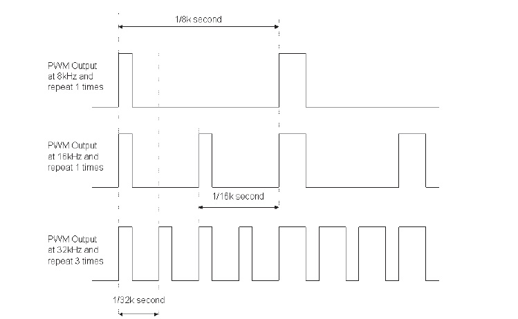
For adequate filtering purposes, the PWM frequency has to be preferably ten times the highest voice frequency present in the sample. Although the audio frequency range is from 20 Hz to 20 KHz, the range of 20 Hz to 3400 Hz is enough for most purposes. So, let’s set the PWM frequency at 40 KHz. Now, the playback rate has to match the sampling frequency rate. This implies that, before changing the duty cycle of the wave being generated, using the next value in the array, three samples have to be inserted in between the current sample and the next sample. These samples can be kept the same as the present sample or can be generated using interpolation. Using interpolation improves the sound quality and reduces distortion. For the next part, let’s assume you have managed to successfully generate the PWM wave.
Next comes the filter. The filter becomes easy to design, due to the wide seperation between the PWM frequency and the frequency range of interest. One can design a filter using software tools like FilterPro provided by Texas Instruments. The higher the order of the filter, the better the audio output generated by the filter. For the filter, one can keep a passband frequency of 4 KHz and a stopband frequency of 5.6 KHz. Keeping the allowed ripple in the passband at 0.5 dB and a stopband attenuation at -45 dB would give a four stage, eigth order filter. Keeping an allowed ripple of 0.5 dB, allows us to use the Chebysev response, for achieving a sharper cut off. Using a Butterworth response, would not give a sharp enough cut off. If you are using FilterPro, try and see what happens if you change those parameters. For example, what happens, if I make the stopband frequency have a value of 5 KHz?
The filter seperates all the high frequency components and leaves us with a waveform which is a rough enough replica of the original signal of interest. You can record the output of the filter by connecting it to the microphone input of your PC and recording it with a player like Goldwave, using which you can also do some pretty cool analysis.
You might be wondering about the assumption I told you about, just in case you still didn’t get it. The number of samples to be inserted in between will depend on the sampling rate. In my case, I used a PWM frequency of 40 KHz, so I inserted four samples in between. Refer the below figure. Depending upon the code you write and how you have to set up PWM for your processor, you might have to scale the values of the array and the bits per sample will be important for this scaling.